Broadband High-Reflection Coating at 50 Degrees

[ Contents ] [ Index ] [ Home ]

In the paper,

    Konstantin V. Popov, J.A. Dobrowolski, Alexander V. Tikhonravov, and Brian T. Sullivan, "Broadband high-reflection multilayer coatings at oblique angles of incidence," Applied Optics, Vol. 36, No. 10, 1 April 1997, pp. 2139-2151.

the authors examine the problem of creating broadband dielectric reflectors using contiguous quarter-wave stacks. It is an interesting paper -- well worth reading if you need to design this type of coating. The following example is taken from the paper.

The goal is to design a high reflector which operates in the wavelength range 400-800 nm at a 50 degree angle of incidence. Because this coating is at 50 degrees, the reflectance of S polarization will be much higher than P. Hence, we can concentrate on controlling the reflectance for P polarization. The coating, composed of layers of L (index 1.45) and H (index 2.35), is to be deposited on glass G (index 1.52). The incident medium is air (index 1.0).

The formulas in the paper lead to a 3-stack (7 periods/stack) design whose stacks are centered at wavelengths 705, 555, and 437 nm. To increase the reflectance, the authors add one additional H layer next to the substrate. The result is a 43-layer coating whose average P reflectance is 98%.

TFCalc can be used to design and refine this type of coating. The starting design is a 43-layer coating with the stack formula

    G a(HL)^7 b(H(LH)^7) c(LH)^7 air
where H and L represent 1 QWOT (quarter-wave optical thickness) at a reference wavelength of 550 nm and incident angle of 50 degrees, and the factors a, b,and c must be determined using "group" optimization. (This is called group optimization because we vary the thickness of a group of layers; all layers in the same group keep the same relative thickness to the other layer in the group.) Using one continuous target (Rp=100% for 400-800 nm at 50 degrees) and starting values of
    a = 1.2000, b = 1.0000, c = 0.8000,
group optimization finds
    a = 1.3260, b = 1.0171, c = 0.7855.
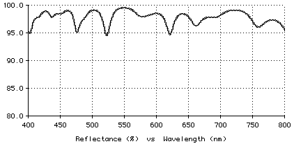
These values correspond to stacks centered at 729, 559, and 432 nm. The average P reflectance is about 98%. The performance for P polarization is displayed below.

Plot of high reflector design

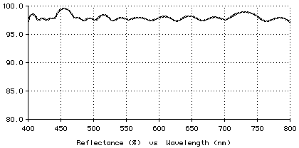
If all layers are optimized to improve the reflectance, the average P reflectance stays approximately the same; however, the minimum reflectance is substantially higher, as shown below.

Plot of high reflector design

Here is the last design, with the first layer closest to the substrate and thickness given in nm.
    H      97.87
    L     171.35
    H      80.56
    L     152.15
    H      74.35
    L     154.04
    H      83.10
    L     178.45
    H      72.02
    L     129.75
    H      85.36
    L     141.64
    H      82.96
    L     141.89
    H      71.17
    L     137.71
    H      69.96
    L     104.04
    H      55.42
    L     113.89
    H      71.53
    L     121.61
    H      63.21
    L     111.11
    H      61.47
    L     121.69
    H      63.51
    L     101.69
    H      56.86
    L     101.16
    H      52.26
    L      82.60
    H      46.62
    L      94.22
    H      53.49
    L      90.92
    H      46.16
    L      86.62
    H      51.59
    L      91.80
    H      45.96
    L      80.64
    H      49.35
Copyright © 1995-2008 Software Spectra, Inc.